BPE and 3A Sanitary Fittings- What’s the Difference?

2″ Elbows, one ASME BPE, one traditional Sanitary 3A. They have the same radius but different length tangents
A topic we’ve focused on a lot in the past is sanitary fittings- both BPE and 3A fittings, but this is still something that comes up a lot as when we talk to customers. People who are not intimately familiar with the industry can struggle to distinguish between regular sanitary or 3A fittings and BPE fittings. This post will cover the similarities and the differences between the two fittings and hopefully clear up a simple misconception.
To start, how are the two similar? Well, both BPE and 3A fittings are considered sanitary. Both are measured in the same way sanitary tubing is- by tube OD. We’ve talked about this in the past. This means you could weld the two fitting types together. The triclamp dimensions for the for the two are also exactly the same- which means whether you’re looking for 3A or BPE fittings, you’re just as likely to confuse 1” or 1.5” fittings. Some of the fittings also have the same overall dimensions. Both the 14WMP and BPE S14WMP short welding ferrules, for instance, have the same OAL.
That is about where the similarities end, we’ll spend the rest of this post highlighting some of the differences between the two.
3A fittings have their roots in the dairy industry. They are marked with the 3A symbol which lets customers know that these fittings are designed specifically for use in the dairy applications. As the industry evolved, an ASME subgroup, known as the BPE, developed their own standards for fittings. These fittings needed extended tangents to accommodate the orbital weld heads used heavily in the autogenous welding procedures used in the joining of pharmaceutical fittings. BPE fittings dimension are requirements are outlined in the Bioprocess Equipment standard. BPE fittings are designed specifically to be fully drainable when properly installed.
Another difference that should be highlighted is material availability. 3A fittings are commonly offered in both 304 and 316 stainless steel. BPE fittings are offered exclusively in 316L SS. The next thing that really sticks out is the end styles. Have you ever seen I line BPE fittings? The answer is no. BPE fittings are available in exclusively butt weld and hygienic triclamp ends. You won’t see the I line, John Perry, or Q line fittings available in other sanitary fitting styles.
Now, let’s talk surface finish. Both 3A and BPE fittings have what we consider “sanitary” surface finish. Sanitary surface finishes are generally considered any finish that is 32 Ra or better. 3A fittings meet this spec and often exceed it. BPE fittings, however, come in several additional flavors. The “standard” BPE finish is the #3 PC or SFF1 finish. The #3 finish has a 20 Ra Mechanical ID polish and an unpolished OD. Some BPE fitting lines, such as VNE’s Maxpure, even feature a light OD polish on their PC and PD fittings (which are generally insulated). The most common BPE finish is the #7 or PL finish. This is a 20 Ra mechanical ID finish and a 32 Ra polished OD. These are the fittings you’ll see on an uninsulated pharmaceutical process skid. After the PL and PC finishes, we get into the electropolish finishes- PL and PM. These finishes feature a 15 Ra ID w/ EP and either polished or unpolished OD’s. These additional finish options are the biggest reason why BPE fittings are generally more expensive than 3A fittings.
Another difference you’ll see between 3A and BPE fittings is the availability of lot and material traceable certs. On 304 3A fittings, you can’t even get heat certs and on 316 they still aren’t always available. BPE fittings, on the other hand, almost never ship without them. VNE’s MaxPure fittings even ship with a QR code on the package that allow a smartphone to almost instantly retrieve the MTR. Material traceability and verification are absolutely critical in the pharamcetuical process world.
So there you have it- just a few of the similarities between BPE and 3A fittings. If you’d like to know more about the differences, give us a call. We also keep the Midwest’s largest inventory of sanitary fittings, tubing, pumps, and valves. Our decades of combined experience will help you to make sure you get the right fitting the first time.
Change Control- A Critical Issue in the Single Use and Pharmaceutical Process Industry
At a recent panel discussion of bioprocessing industry experts regarding the evaluation of stainless vs single use process components, one panelist was asked an interesting question- when evaluating a single use validation package, what piece of information do you consider to be the most critical? The panelist’s answer may surprise you. While many in the audience may have guessed USP Class VI testing or leachables and extractables studies, this panelist (a category engineering manager for a major pharma company), responded that vendor change control procedures were most important to her when evaluating a new product for their process. This blog will take a look at the why documentation of change is important and what events can trigger a change
To begin, what is a change and why does control of change matter? The pharmaceutical process industry is one of the most tightly regulated industries in the world. And for good reason- patient’s lives may ultimately depend on the quality of decisions made by the people who are responsible for the quality of products and the processes used to manufacture them. A “change” may be a simple adjustment to accommodate a customer specification, an updated document, a part replacement, or other production change. It may result from a deviation from an SOP or work instruction. A change may be temporary or permanent, routine or emergency.
Because change is an inevitable event in any manufacturing process, control is critical. Changing of a process is complex and communication of the change to key stakeholders can be equally challenging. For that reason, it is absolutely essential that clearly defined systems exist that manage how changes are implemented and how they are communicated to stakeholders.
So what are some common events that may result in the need for a manufacturer to send a change notification to an end user, you may ask? Those may range from benign to the extreme- product discontinuation or recall. A few examples of changes that a manufacturer is generally expect to notify a customer prior to implementing include changes in labels or packaging of a material, change of company name, change in shelf life, or changes concerning storage conditions.
While a simple “heads up” may work for some changes, others require more advanced notification- usually a minimum of 6 months. Examples of these sorts of changes include the change of a critical subcontractor, new edition of an analytical specification or product test method, or change regarding animal origin of a raw material. Other changes, such as changes in test methods, elimination of a test method, change in manufacturing site, change in raw materials, may necessitate notification of stakeholder of 9 months or more in advance of a change.
For a distributor like Holland, it is equally important that we have systems in place to handle changes the companies we represent make. With hundreds of active open accounts, it’s critical that we act have clearly outlined and detailed procedures for handling a change made by a manufacturer and getting that information to our customer’s so they can take appropriate action .
To conclude, at Holland, we understand that manufacturers are being continually pushed to develop innovative, high-quality products at lower costs. Whether it’s to stay competitive or to enter new markets, manufacturers need to make changes to meet customer demands. We understand that having a robust quality system is essential to both our success and our clients. If you have any specific questions regarding our quality systems or change control guidelines, contact a Holland Sales Engineer today.
National Welding Month- The History of Welding

Welding Piping Hangers on a Sanitary Skid Using the Manual TIG Technique
For our next spurt of blog posts, we’re going to focus on one of mankind’s greatest inventions-welding (welding actually ranked #10 on Scientific American’s list of greatest inventions back in 2013). With April being National Welding month, we’re going to take a few posts this months to talk about the history of welding and then focus more specifically on sanitary welding and welding in the high purity process industry.
The history of welding goes back to the Bronze Age. Man’s first attempts at joining metal were done mostly through a process known as forge welding. It works by heating the metal pieces until they glow red and soften. When they’re soft enough, the welder mashed the two parts together with a hammer and allowed them to cool. This type of metal working was popular up until the Industrial Revolution when new forms of welding were devised to meet industries evolving needs.
While the history of welding is interesting, we’ll spend the rest of this post focusing on the common welding techniques of today and where we see them used.
The easiest place to start is the welding process we’re most familiar with- arc welding. Arc welding is a type of welding that uses a power supply to create an electric arc between an electrode and a base material to melt the metals together at the welding point. There are two main methods of arc welding- consumable and non-consumable electrode methods. An example of consumable welding is gas metal arc welding (GMAW), also known as MIG (metal/inert-gas). This is a semi-automatic or automatic process in which a continuously consumed wired is fed and acts as both the electrode and filler metal. At Holland we use MIG welders to join structural material, like stainless steel skid frames.
The most common type of welding we see in the high purity industry is another form of arc welding that uses a non-consumable electrode and separate filler material to join two parts. Known as gas tungsten arc welding (GTAW) or tungsten/inert-gas (TIG) welding, TIG welding is a manual process that uses an electrode made of tungsten, an inert gas mixture. TIG welding may or may not use separate filler material to affix joints. This process is especially useful for welding thin materials, but because it is a manual process (with the exception of orbital welding, which we’ll touch on later), it requires a significant amount of skill and can only be accomplished at relatively slow speeds, relative to MIG or other welding processes.

Welding a High Purity Piping Component in Our Shop Using a Computerized Orbital Welder
As we just mentioned, another method of TIG welding common throughout the biopharmaceutical industry is orbital welding. Orbital welding is an automatic process whereby an arc is rotated mechanically 360 degrees around an unmoving work piece. This technique does not use a filler material. By taking the human out of it, we see consistent, high quality welds that require little operator intervention. Orbital weld beads end up being so smooth and consistent that BPE guidelines don’t even make us polish ID welds. Most of the high purity welds we create for bio pharmaceutical skids and modules are automatic orbital TIG welds
Now that we’ve talked about arc welding, we’ll spend the rest of the post focusing on some processes that are less common in the high purity industry, but pretty cool nonetheless.
The first process we’ll touch on is friction welding. Friction welding uses pressure and movement to generate the heat we need to cause welding to occur. Friction welding is commonly used to join dissimilar materials. This is helpful in aerospace applications where we might want to join a lightweight aluminum part with a high strength steel. Because of the large difference in melting points between aluminum and stainless, arc welding procedures would be useless and a mechanical connection would be required. But friction welding provides a full strength bond with no additional weight.
Next, let’s look as laser welding. We do see laser welding from time to time in the sanitary industry. Laser welding is a process that uses a high power laser beam to provide a concentrated heat source, allowing for narrow, deep welds and high welding rates. Because of its speed, laser welding is commonly used in high volume applications. Laser welding provides high quality welds and the focused beam results in small heat-affected zones, resulting in little distortion of the part.
Finally, we’ll talk about ultrasonic welding. Ultrasonic welding is cool because it is commonly used to join plastics and dissimilar materials. Ultrasonic welding uses high frequency ultrasonic vibrations applied to work pieces held together under pressure to create a weld. We think ultrasonic welding is interesting for its potential uses in affixing single use needle hubs to cannula.
This is by no means a comprehensive list of welding techniques, but a brief overview on a few processes that we see in our industry or just think are cool. We’ll spend the next couple of posts discussing sanitary hand and orbital welds a little more closely. If you have any questions about your sanitary welding application, contact a Holland Sales Engineer today
Product Focus- Quattroflow 1200 “Compact” Pump

Quattroflow QF1200CV Pump
In today’s blog, we’re going to revisit a product we’ve focused on in the past- the Quattroflow quaternary diaphragm pump. The Quattroflow series of pumps is one of our newer products offerings that continues to innovate, offering our biopharmaceutical customers scalability, flexibility, and performance that traditional product offerings can’t match. As Quattroflow gains larger market acceptance, they have continued to push the envelope to meet customer demands and bring new products to market. Today we’ll take a look at their latest product offering- a compact version of their popular QF 1200.
For some time now, the Quattroflow pump has been available in the 150, 1200, 4400, 5050, and 20K sizes, with all but the 20K being offered with both stainless and single use heads. The smallest of these sizes, the 150 is offered with an integrated drive and controller standard. This small footprint and wide turndown makes the 150 perfect for lab and low flow applications.
When we scale up to the QF1200, however, the Quattroflow 1200 has traditionally been offered with separate pump and control boxes. The 3 phase, 0.5 HP motor meant that we needed to use a variable frequency drive to achieve the wide ranging turndown the Quattroflow is known for. While this is an effective solution, it meant we would need two enclosures- one for the pump and one for the VFD. This relatively large footprint presented challenges when mounting the QF1200 to a skid or when trying to make room for it on an already crowded lab bench.
To solve this problem, we are now excited to offer the Quattroflow 1200CV. Similar to the QF150, the QF1200CV combines controller, motor, and pump into an all-in-one unit that is perfect for customers with a tight space requirement. The compact version of the QF1200 uses a brushless DC motor that is similar to one used in the QF150 and affords use the same range, turndown, and low pulsation the Quattroflow pump is known for.
Currently offered with a single phase, 220V motor, the QF1200CV is available with an optional 0-5V DC input for speed control (which can be easily scaled to a 4-20 milliamp input). The QF1200CV is available with standard ¾” TC stainless and single use heads. Single use heads are available in both a machined polypropylene as well as an injection molded polyethylene. The polypropylene chamber is ideal for high temperature and SIP applications, while the molded head is economical and ideal for applications where the chamber will be gamma irradiated and disposed of following a campaign. All soft parts for both the single and multiuse heads are fully characterized, made of USP Class VI materials with extractable and leachable reports available.
To conclude, the QF1200CV adds another option and flexibility to one of the most scalable positive displacement pump technologies on the market. If you have questions about your next biopharmaceutical application or to see if the Quattroflow line of pumps is right for you, contact a Holland Sales Engineer today.
NPSHA- What is it and What can I do if I Don’t Have Enough?
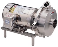
Sanitary Centrifugal Pumps Can Operate Effectively with Less Than a Full Atmosphere of Suction Pressure, but They Must Maintain Their Prime
We’ve talked plenty about sanitary pumps in this blog in the past. One topic we’ve touched on, but haven’t explicitly detailed, is NPSHA. Today’s post will focus on what NPSHA is and how it applies to your sanitary pumping application.
To begin, NPSHA stands for Net Positive Suction Head Available. NPSHA should not be confused for NPSHR, which stands for Net Positive Suction Head Required. NPSHA is a measure that corresponds to the level of pressure at the sanitary pump suction. The high the pressure the gauge at the pump suction reads, the higher the NPSHA, and the better the pump will operate. This pressure can be easily measured with a gauge at the pump inlet. Remember, most pressure gauges scales to atmospheric pressure, meaning they read zero when there is no pressure other than atmosphere (14.7 psi). In most cases, we can assume gravity will give us 34 ft of head.
The most important part of NPSHA is the head component. We’ve talked about fluid head in the past, and for NPSHA, the component of total head we’re most interested in is static head. The static head is the distance between the fluid level and the inlet of the pump. Generally speaking, the greater the static head, the greater the NPSHA.
After we know what atmosphere is giving us and how much static head we have, we need to net out or system losses. This is mainly friction loss. We’ll lose head as the fluid flows or is restricted through the system. The most common friction loss adders include, elbows, valves, and strainers.
So once you know what your NPSHA is, how do you know if you have enough? Well, that is where NPSHR comes back in. The pump manufacturer tests the pump under various suction head conditions and provides a requirement or NPSHR for each flow condition on the pump curve. All we have to do is check our NPSHA against our NPSHR and we’ll know if we have enough. Most pumps can operate with a suction pressure that is below atmospheric (below 34 ft or 14.7 PSIA). In these situations, however, it is very important to keep the suction line primed through the use of foot or check valves.
So what happens if in your pump application you don’t have enough suction head? What do you do? Well first, it will be pretty apparent, especially with centrifugal pumps, because you won’t be getting the flow you expect out of it. You may also have pump cavitation. It will sound like marbles are going through you pump.
So how do we fix it? Well, one factor that is commonly overlooked is supply tank level control. You may start out with a full vessel and have plenty of NPSHA, but as fluid is moved the level in the tank decreases, our NPSHA will also fall. To solve this, we can control the tank level with either point or continuous level sensors, or we can raise the height of the tank so that we’ll have enough suction head even at low tank levels. Another solution would be to lower the level of the tank inlet relative to the tank fluid level. You could also pressurize the vessel to juice your NPSHA.
Another issue we see often is locating elbows or fittings too close to the inlet of the pump. Fittings, such as 45’s, 90’s, and valves will all detract from the NPSHA. We recommend minimizing the number of fittings leading up to the pump. We also want to locate the pump as close as possible to the tank, avoiding long straight lengths leading up to the pump. We also want our suction line to be as large as possible. This is why the inlet of a sanitary pump is usually larger than the discharge.
So there you have it- a detailed overview of most everything you’d want to know about NPSHA in your sanitary application and how you can fix the problem. Remember, if you’re experiencing noisy operation, capacity loss, or pitting, check to make sure you’re supplying adequate pressure to the inlet pump. If you have any additional questions about your next sanitary pump application, contact a Holland Sales Engineer today.
How Do You Identify an Old APV Homogenizer?
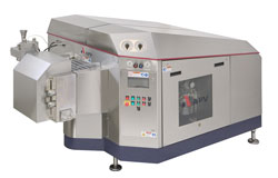
APV Homogenizer
Some of the most interesting requests we get every day at Holland are about the piece of equipment we sell that tends to have the longest life span- an APV High Pressure Homogenizer. The APV Gaulin and Rannie type machines are the well-built work horses of many food, pharmaceutical, and personal care products where a stable emulsion or mixture needs to be created. Because they are so critical to the process (as well as the large upfront cost), it is not uncommon for homogenizers to be in service for 20, 30, sometimes even 40 years. There is also a sizeable aftermarket for high pressure homogenizers, so we frequently have customers who are not the original owners of their machine. Fortunately, the good folks at APV and SPX have made it easy for us to identify a machine and spare parts based on its unique serial number. This post will discuss the APV homogenizer serial number system and where to look on your machine to figure out which machine you have.
To begin, let’s talk about where you look on your machine to find the serial number. Generally speaking, on cast iron or painted frame machines (those old blue beasts), the serial number will be found stamped on the top frame edge, on the right hand side facing the cylinder block. The machine identification tag is located on the rear wall of the plunger well. Machines with a stainless steel or mild steel skin (newer machines), will have the serial number stamped on the left side of the base casting, just above the motor compartment. Many newer machines will also have a tag calling out the serial number.
So now that we know where to find the serial number, let’s talk about what those numbers mean. Since 1939, APV has been using a four digit serial number on all production scale Gaulin homogenizers. There are about 68 machines that are an exception to that rule from 1959 and all machines made at 1986 have had 5 digit serial numbers. That means the last 3, 4, or 5 digits are the unit serial number. The numbers preceding the serial number indicate the date of manufacture. For example, let’s say you pull the number 10757-927 off of your machine. That would mean that this machine was built on January 7th, 1957 and the serial number is 927. The month, day, and year were used until 1960, after that, only the month and year were used (for instance, 157-927).
So hopefully this helps you better identify your APV homogenizer or at least gives you an idea where to look. When order spare parts or making changes to your machine, the model and serial number are the two most important pieces of information you can provide a customer service person at Holland. If you have any additional questions or needs for your sanitary high pressure homogenizer, contact a Holland Sales Engineer today.
Service Reminder- Holland Applied Technologies now offers Sanitary Magnetic Trap Verification

Cesco Sanitary Mag Trap
We’re going to talk a little bit about a service Holland has been offering for some time- Magnetic or “Mag” trap verification and validation. In today’s blog, we’ll give you an overview of how sanitary mag trap testing is performed, why you should have it done, and our current service offerings.
To begin, sanitary magnetic or “mag” traps have been used in the food processing industry for quite some time to prevent two things- adulteration of product and process equipment protection. Keeping metallic objects out of your product not only protects consumers, but also brand name risk and costly recalls. Mag traps will also protect pumps, valves, and instruments from damage. This helps avoid downtime and other costly repairs. Because most customers are familiar with a Mag Traps and what they do, the rest of this post will focus on how we test them.
Historically, there have been two ways to measure magnet strength- the pull test and through the use of an electronic device known as a Gauss meter. The pull test method is used to determine the relative strength of a magnet by approximating the holding force through the use of a scale and spacers. This method is not quantitative, presents a pinch hazard for operators, and is generally not accepted by 3rd party auditors.
While the pull test method has been used since the 1960s, recent improvement in microelectronics have brought economical, portable gauss meters to market. A gauss meter is an electronic instrument that measure the number of lines of magnetic flux emanating from a magnet. A gauss, as alluded to previously, is the number of magnetic flux lines per square centimeter. Gauss meters are definitive, accurate, and repeatable. They can also be calibrated by instruments traceable to NIST and in accordance with accepted ISO standards. Gauss meters are also capable of taking measurements of over 10,000 gauss, which is common with the rare earth magnets used in modern Mag Traps.
Due to increasing food safety concerns and requirements by 3rd party auditors, third party mag trap verification has become an increasing request from out customers. In response to this need, Holland has incorporated gauss meter testing and mag trap verification into our already robust quality and calibration programs. Holland offers digital gauss readings and verification both on at our facility or at our customer’s facility using our in-house DC gauss meter.
Verification starts with visual inspection of trap elements for and signs of pitting, cracking, or other wear to ensure the magnets are intact, followed by measurement of all magnetic probes with a DC gauss meter. Due to our close relationship with several mag trap OEMs, including Cesco, we’re able to reference our readings to the measurements taken when the unit shipped to ensure the magnets are still performing like new. Following testing, we provide a certificate of verification and include meter calibration certs in the turn over package as well.
As mentioned above, we are proud to offer this service both at our facility or our customer’s and we’ve traveled as far as Trinidad and Tobago to do on site testing. If you have any additional questions about our Magnetic Trap verification service offerings, please contact a Holland Sales Engineer today.